


Making ACSI cable
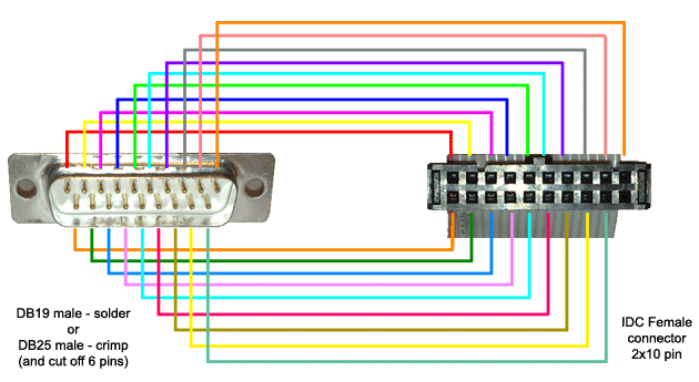
Normal DMA cable for UltraSatan has a simple 1:1 connection between the DB19 female connector and the IDC female connector, this means that the left upper pin of DB19 is connected to left upper pin of IDC connector, the left lower pin of DB19 is connected to left lower pin of IDC connector, and the right upper pin of DB19 is connected to the right upper pin of IDC connector; meaning that the 1st row of DB19 is connected to 1st row of IDC, and the 2nd row of DB19 is connected to second row of IDC.
To make this cable use flat 20-wire cable, which you just put in the IDC connector and push the parts of IDC connector together using i.e. jaw vice.
If you choose a DB25 female crimp connector, cut away the last 6 pins which are not needed and use the jaw vice again to connect the cable.
If you choose a DB19 female solder connector, then solder the 1st wire to the 1st pin in the top row, the 2nd wire to the 1st pin in bottom row, the 3rd wire to the 2nd pin in top row and so on…
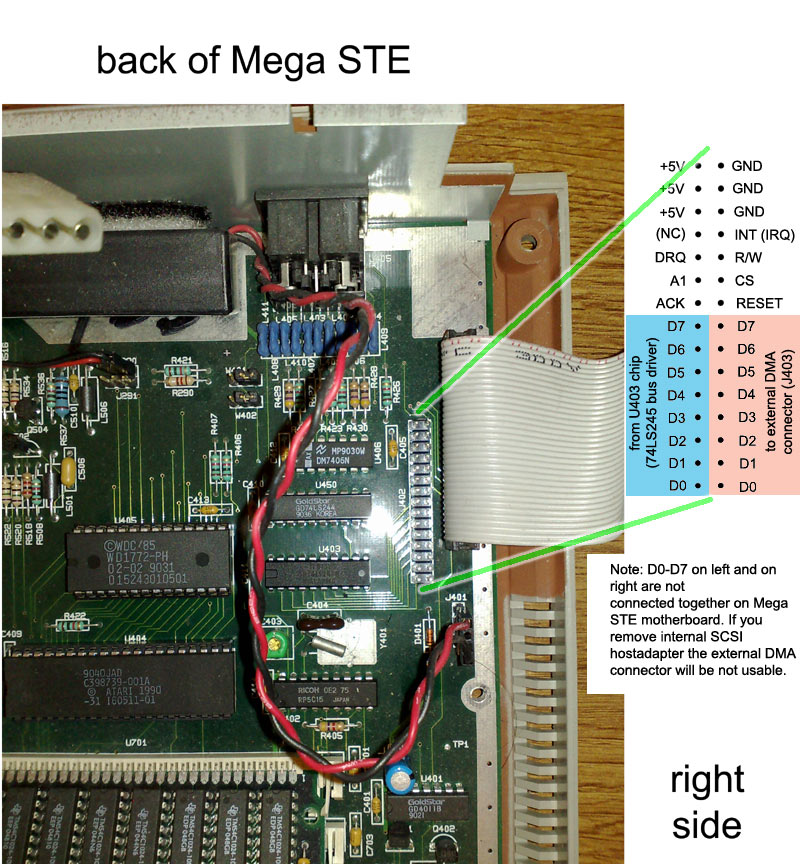
Making the internal data cable for Mega STE consists of two steps:
- making a 20-wire IDC to IDC cable
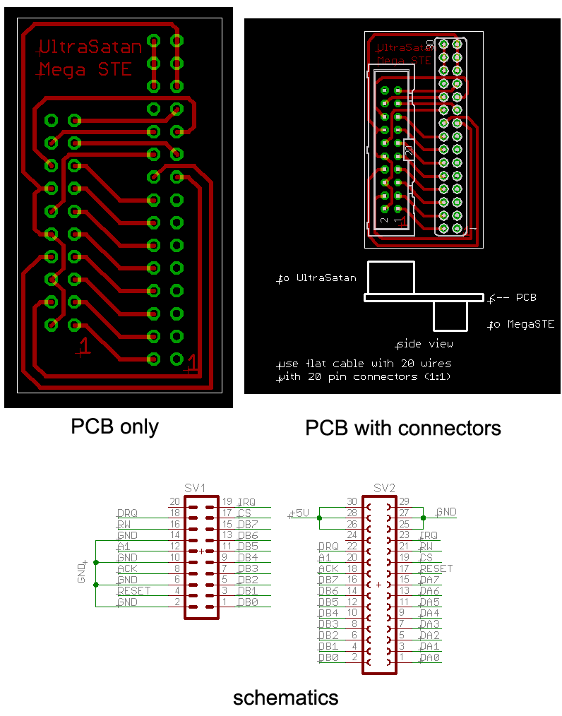
- making a small convertor PCB with two connectors
Making the 20-wire ribbon (flat) cable with IDC 20-pin female connectors at both ends is the easier part – put the cable in the IDC connector and push the parts of IDC connector together using i.e. jaw vice, then do the same for the other other IDC connector.
Then you have to make the PCB, which will have the a 2×15 female header connector on the bottom of PCB and 2×10 male connector on the top. The simple PCB can be found bellow as images, or you can download it as Eagle CAD files here: megaste_cable. Or you could just buy the female header connector and solder the appropriate wires from the flat cable to it.
Note: When you remove the internal SCSI host adapter from Mega STE, the data bits (D0 – D7) on left of the internal ACSI connector will not be connected to the data bits on the right and thus the external DMA connector on MegaSTE will be unusable. A simple help might be just connecting those data bits with wires (and it might work), but the SCSI host adapter uses a 74HCT245 bus driver to connect those data lines together. This bus driver could be added to the PCB convertor but it requires some additional logic to merge CS and ACK signals to the ‘G’ signal of 74HCT245…
 |
 |
Making the cable for Mega ST is very similar to making cable for Mega STE. So you first create that 20 wires ribbon cable with the same IDC female 20 pin connectors on both sides, then you make a small PCB with connectors according to the Eagle CAD schematics (megast_cable) or pictures bellow. The internal ACSI connector is directly connected to the external ACSI connector, so no additional logic is needed (compared to Mega STE).
 |
 |